Lasertex HPI-3D laser interferometer. Range 0-30M ( 80M Available) Resolution 0.1 nm, Accuracy 0.4 ppm, With Tripod, Wireless connection to a PC, Native resolution of 100 pm, Measurements of vibration up to 100 kHz, Dynamic measurements up to 100 000 samp
Manufacturer=Lasertex|Distance Range=0-30 (80) m |
Distance Resolution=
0.1 nm |
Distance accuracy=0.4 ppm|
Angle Range=Angle ±5
º |
Angle Resolution=0.001 arcsec |
Angle Accuracy=0.1 ppm|
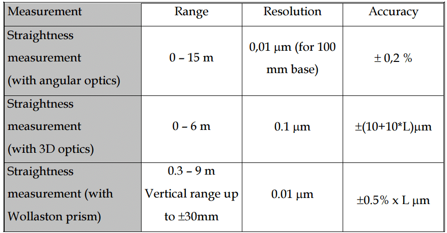
Straightness (angular kit) Range=0 – 15 m|
Straightness (angular kit) Resolution=0.01 um |
Straightness (angular kit) Accuracy=0.5 %|
Straightness (3D option) Range=0 – 5 m |
Straightness (3D option) Resolution=0.1 um
(5 ± 10 ∙ D) μm|
Flatness Range=0 – 15 m |
Flatness Resolution=0.01 μrad |
Flatness Resolution=0.01 μrad |
Flatness Accuracy=0.2 %|
Squarness Range=0,3 – 9 m |
Squarness Resolution=0.01 μm/m |
Squarness Accuracy=0.5 arcsec |
Laser source= Helium Neon laser tube|
Laser power =< 1mW|
Short term frequency accuracy =< 0.001 ppm|
Long term frequency accuracy= < 0.01 ppm|
Operating temperature =0 – 40
º
C|
Operating humidity =0 – 90 % non condensing|
Weight 2000 g|
Dimensions =45 x 70 x 254 mm|
Compensation unit=
Air temperature range 0 – 40
º
C|
Air temperature accuracy= ±0.15
º
C|
Air pressure range =920 – 1060 hPa|
Air pressure accuracy =±1 hPa|
Air humidity range= 10 – 90 %|
Air humidity accuracy =±5 %|
Material temperature range =0 – 40
º
C|
Material temperature accuracy= ± 0.1
º
C|
Peacock NB Metric Calibration Tester 0-20mm (855-620)
Steinmeyer BMG - Manual Version Tape calibration gauge, Code 76 8145 462 20, 0-2000mm resolution 1 μm tensile loading N, 20 N or 50 N
Lasertex HPI-3D laser interferometer. Range 0-30M ( 80M Available) Resolution 0.1 nm, Accuracy 0.4 ppm, With Tripod, Wireless connection to a PC, Native resolution of 100 pm, Measurements of vibration up to 100 kHz, Dynamic measurements up to 100 000 samp
Laser Measurement System HPI-3D is an result of more than 20 years experience in the field of high quality laser interferometers. The instrument represents a “know-how” in the laser measurements field featuring best parameters, highest quality, very rich set of parameters and options, ease of use and compactness. Instruction and full softwareversion available.
Performance
No more limits during measurements! HPI-3D shifts the frontier of parameters available in modern laser interferometers. Extremely high measurable movement speed, ultra high resolution and very high sampling rate make the device suitable even for highly demanding applications.
HPI-3D is able to measure objects moving with speeds up to 7m/s with the standard resolution of 100pm. Automatic compensation of environmental conditions is performed one hundred thousand times per each second. Vibrations of frequency up to 50 kHz can be easily measured. Even better parameters are available on request!
Versatility
Although there is no universal measurement device but the HPI-3D comes close. The instrument can be used for measurement of long (tens of meters) and extremely short (hundreds of picometers) distances, for detecting very high and indefinitely slow movement, for monitoring vibrations, measuring angle, comparing distance, testing straightness, flatness, squareness, parallelism and many more. The laser can be used in scientific laboratories, machine industry halls and in the open air. Not only can it be controlled by a PC, tablet or a smartphone but its functionality can be modified by the user in many ways.
Ease of Use
The HPI-3D was designed with the emphasis on user-friendliness and portability. The instrument has built-in wireless connectivity and can work with or without PC connection. It can be mounted directly on the measured object (e.g. inside a machine) simplifying the measurement path and allowing to spare on the alignment time. The laser is available in a small and sturdy transportation case offering superb portability. Easy to use, yet powerful PC software make the usage of the complete device an easy task even for inexperienced users.
Applications
Positioning of CNC and CMM machines
Machine geometry inspection
Rapid assessment of machine geometry
Flatness measurements
Axes parallelism measurements
Angular positioning
Ball screw inspection
Machine servicing
Vibration measurements
Straightness measurements
Squarness measurements
Dynamic measurements with internal or external strobe
Small angle measurements
Variety of laboratory applications
Features
Native resolution of 100 pm (higher on demand) obtainable at all speeds – Basic resolution of HeNe laser based laser interferometers is 158,2nm. The HPI-3D utilizes a special combination of heterodyne and homodyne optical configurations in order to achieve a basic resolution of 100pm for single pass optics and 50pm for double pass optics with a superb, sub nanometer measurement linearity. The signal processing path of HPI-3D allows achieving maximal resolution at any measured speed.
Measurements of vibration up to 100 kHz – When connecting HPI-3D over USB port it is possible to monitor vibrations of a measured object at frequencies up to 100 kHz with resolutions down to picometers. Such parameters allows using the instrument in the field thus far reserved for specialized laser vibrometers. Additionally a specialized optics with very light reflecting element for improved accuracy can be used.
Dynamic measurements up to 100 000 samples per second –A CNC or CMM machine is a dynamic object that requires to be characterized with the use of proper tools. HPI-3D offers unique capability of monitoring machine parameters like position, velocity or acceleration every 10 microseconds for practically indefinite time. The information gathered in the dynamic mode of HPI-3D can be used for further analysis with the use of specialized mathematical software.
Max measurable velocity up to +/- 7m/s (up to +/- 20m/s on demand) –In today’s industry there exists a clear trend of increasing speed of CNC machine processing. Testing of those machines requires an instrument capable of handling high or very high movement speed. HPI-3D with its unrivaled high frequency architecture offers a standard measurable velocity of +/- 7m/s and an option of an unimaginable +/- 20m/s!
Rapid estimation of machine geometry with 3D subsystem – An inherent and very unique part of the HPI-3D is the subsystem for measurement of the position of the laser beam in space. The instrument is capable of simultaneous measurement of the reflective element position change in all three directions making possible rapid estimation of machine geometry with the use of the simplest linear optics. Machine geometry parameters like: straightness, squareness or parallelism can be easily assessed.
Configurable encoder output – HPI-3D interferometer can function as a replacement of magnetic and glass scales, i.e. as a high-precision laser encoder. The encoder output is fully configurable from the HPI Software with simultaneous differential digital and differential analog outputs. The maximum frequency of the digital output can be as high as 25 MHz.
Integrated environment compensation unit with wireless sensors – High precision laser interferometer measurements require the use of air temperature, pressure and humidity sensors. Additionally a few base temperature sensors are also recommended. HPI-3D integrates, in standard configuration, an environment compensation unit together with maintenance free wireless sensors.
Wireless connection to a PC (USB can be used as well) – HPI-3D offers user a flexibility of choosing the method for connecting the device to computer. If the performance is the issue then the classic USB cable connection can be used. For the simplicity and ease of use a wireless Bluetooth interface is available. Each choice is right!
User friendly software – The HPI Software has been and is developed on the base of the constant feedback from users. It is simple to use yet with rich set of features. Measurements and analysis are performed from a single application with common driving interface – easy and fast!
Communication protocol and drivers available for the user – For certain applications the rich functionality of HPI Software may be not enough. In those cases the user can built its own software utilizing functionality of the HPI-3D. The necessary drivers and programming API is available
Free software updates avaialble through the www.lasertex.eu webpage – The full and unlimited version of the HPI-3D software is always available for download through the www.lasertex.eu webpage. The new, improved versions are available on the webpage regularly and available at no cost
Compact construction – laser head integrates distance measurement, environmental compensation and encoder output paths
Portability in a small and sturdy case – HPI-3D is a highly integrated device with many functional modules placed in a sturdy case. The device is designed to be easily transportable. The case consisting the complete laser with linear and angular optical components, environmental sensors, power supply and necessary cables has a volume of 40 volume and weights 10kg
Wide range of available optical components (single and double pass configurations) – HPI-3D is a device allowing many different measurements. Full functionality of the laser interferometer depends on the utilized optical configuration. Usually the simple linear configuration is used but there exists tens of possibilities. The optical elements are offered either as standard components or on user demand
User configurable inputs/outputs – The versatility of the HPI-3D reaches new limits with over a dozen of user configurable digital input/output pins. The functionality of those pins can be modified at any time with the use of HPI Software and is remembered in the non-volatile memory. Through the pins the laser head can be used, for example, to drive stepping motor or to monitor the state of external sensors
Integrated system for measuring position of laser head in space (rotation, elevation) – The most difficult part of each laser interferometer measurement is the alignment of the laser beam path. One of many beam path alignment supporting tools in the HPI-3D device is the built-in indicator of the laser head position in space. It showing the rotation and elevation angles shortening the measurement set-up time especially on more complex machines.
Integrated system for measuring position of laser beam – An important part of the HPI-3D is the beam position measurement subsystem allowing instantaneous measurements with the laser in three directions (i.e. along and perpendicular to the laser beam). The 3D subsystem is responsible for improving the measurement accuracy of the laser, for delivering straightness data and for simplifying beam path alignment
Integration with an external electronic spirit level – New feature allowing simultaneous measurement of laser interferometer and high accuracy electronic spirit level in the HPI Software. It is now possible for example to control the level, pitch, yaw or roll during single yet simple measurement!
The influence of the outside conditions on the measurement accuracy
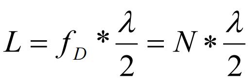
According to first equation an interferometer’s unit of measure in length measurement is laser’s wavelength.
Where: N – number of pulses, lambda- light wavelength.
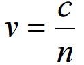
From definition a wavelength depends on laser’s frequency f and the speed of light v in the measuring path.
If the measurement is done in vacuum, than v= c = 3*1G m/s. The speed of light in a medium other than vacuum (e.g. air, water) is lower and is described as Where: n – a refraction coefficient.
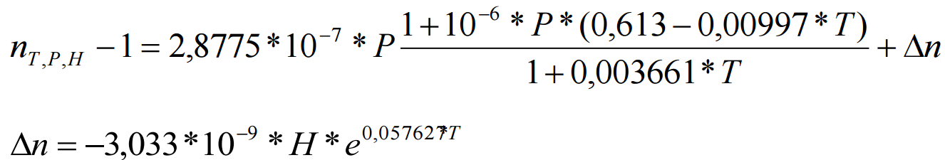
Normally the refraction coefficient n is a complex variable or even a tensor, but for less accurate calculations it is simplified to a constant. The air coefficient depends mostly on the pressure P, temperature T and humidity H. The dependence , for the air was empirically determined by Edlen and is described as
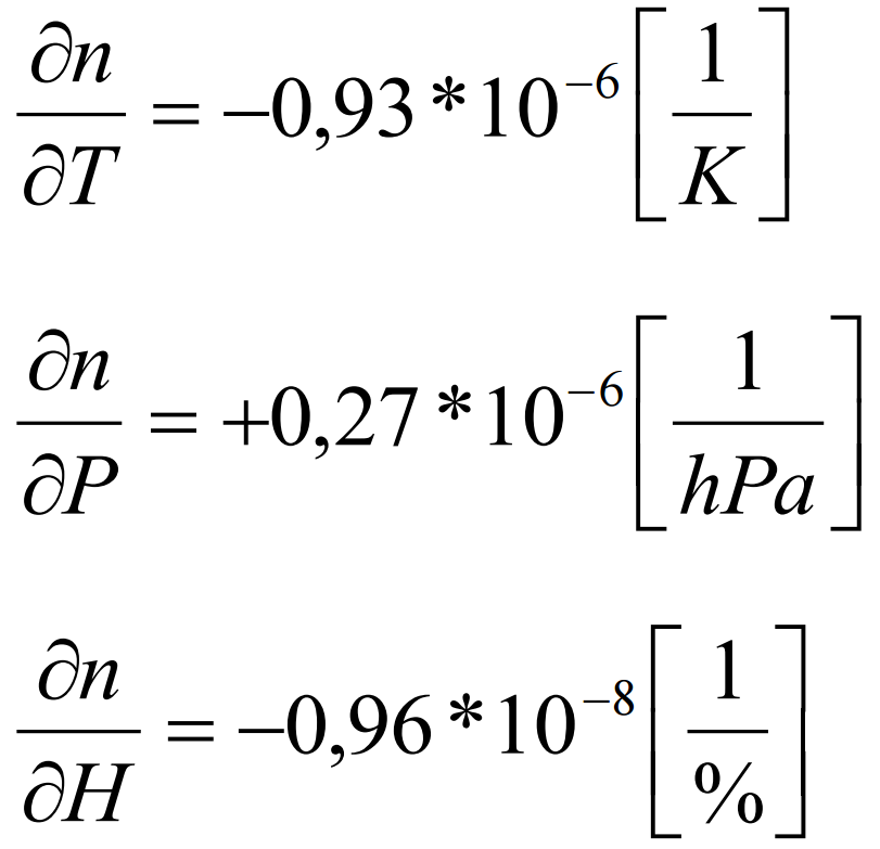
From the above equations one may obtain the refraction coefficient dependences on T, P and H in usual conditions (T=293K, P=1000hPa, H=50%):
It is worth to notice that the most critical parameter is the temperature, because its change influences the coefficient n more than changes in the pressure and much more than changes in the humidity.
The rules of laser displacement measurements
Theory
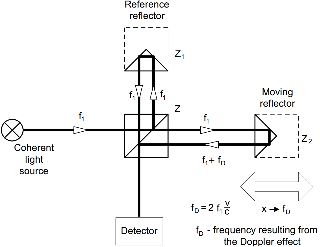
Displacement measurements with the use of a laser interferometer allow obtaining the accuracy of a displacement measurement of 0.4 ppm in air and 0.02 ppm in vacuum. The interferometer was first built by A.A. Michelson in 1881. The simplified schematic of the interferometer is shown in the figure below. Coherent light beam falls on a semi-transparent mirror. This mirror splits the light into two beams. The first goes to the reference arm and reflects from the reflector Z1; the second goes to the measurement arm and reflects form the reflector Z2. The reflected beams meet again on the detector. Because these beams come from the same, coherent, source, they will interfere. When the moving reflector is being displaced, the frequency of the reflected beam in the measurement arm changes. The detector counts the frequency difference between reflected beams – fD. The measured value of the displacement is calculated according to:
Where: N – number of pulses, l – light wavelength.
Construction of real interferometer
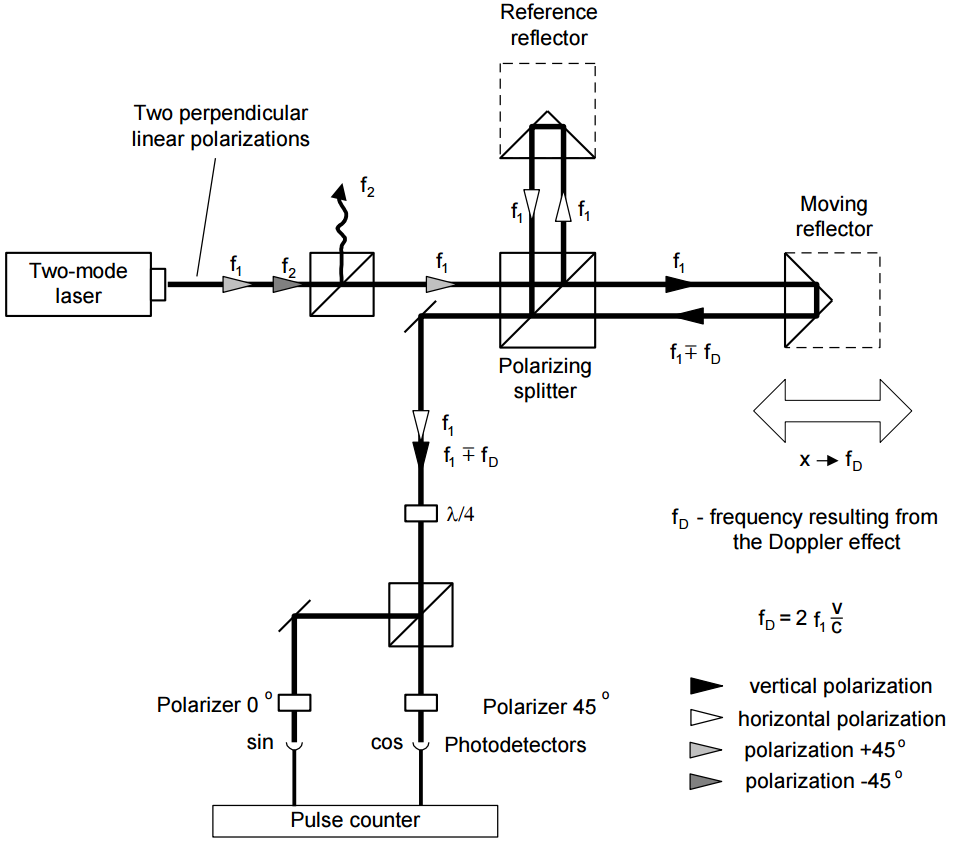
The main disadvantage of Michelson interferometer results from the fact that the detector cannot determine, whether fD is negative or positive thus, from the measurements the displacement of the moving reflector without the sign is obtained. Currently there are widely used two methods that allow getting also the direction of the movement. Depending on the number of light frequencies (wavelengths) used in the interferometer, the first is called homodyne (one frequency) and the second heterodyne (two frequencies) method. In the homodyne method, shown on figure below, as a coherent source of light a linearly polarized laser is used. If it is two-mode laser (i.e. it generates two wavelengths) than one mode must be cut off with the use of a properly set polarizer. The polarizing splitter splits the light beam from the laser into two beams polarized vertically (90°) and horizontally (0°). The former is directed to the measurement arm and the latter to the reference one. The frequency of the beam in the measurement arm changes with the movement of the moving reflector. The polarization of the reflected beams is changed to circular with the use of a l/4 waveplate. After 0° and 45° polarizers, two signals shifted in phase are obtained. The phase shift is +90° when the measurement arm moves to and -90° when it moves from the laser.
THE BLOCK DIAGRAM OF AN INTERFEROMETER WORKING ACCORDING TO THE HOMODYNE METHOD
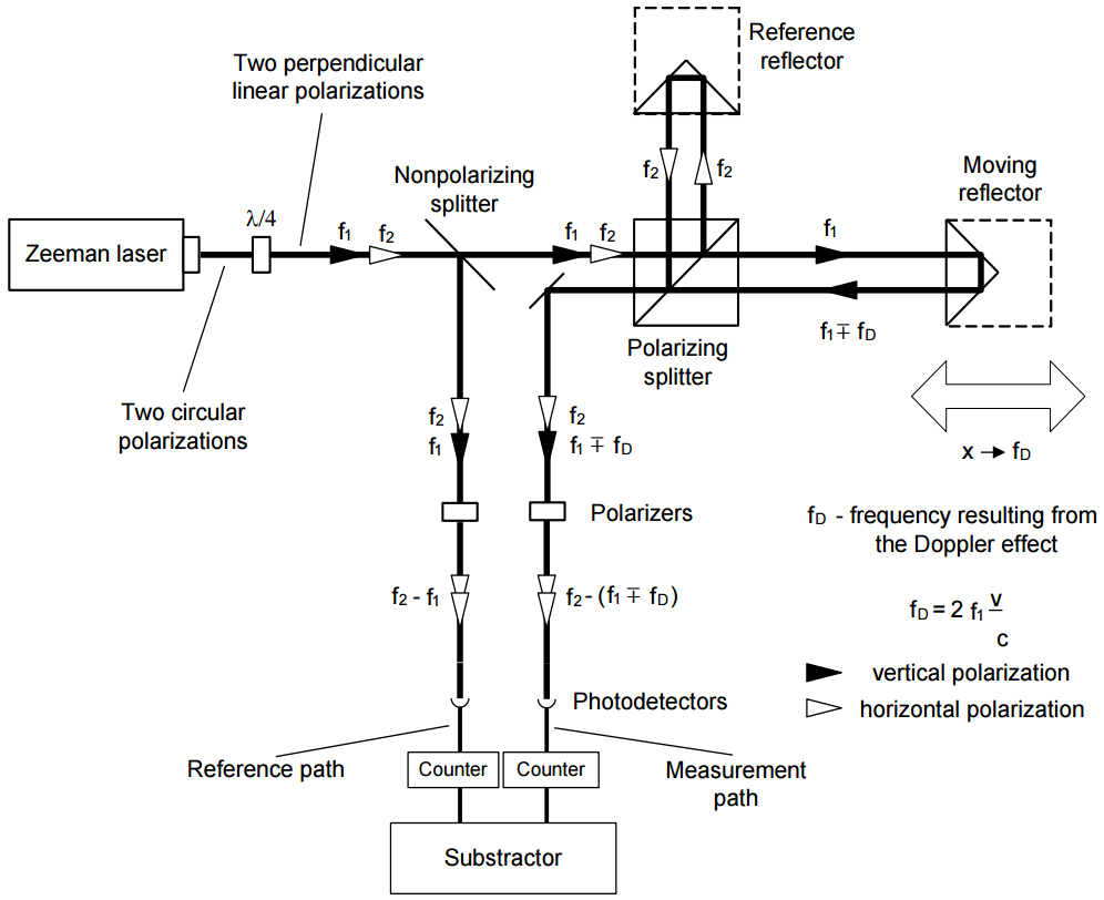
In the heterodyne method, shown on the next figure, two laser frequencies are used. Therefore a two-frequency laser is needed, e.g. a Zeeman laser. A two-mode laser is not suitable for the heterodyne method interferometer, because the difference between f1 and f2 is usually too high for an electronic counter. The output beam of a Zeeman laser consists of two circularly polarized beams, one polarized leftward and the second rightward. A lambda/4 waveplate changes circular polarization to linear. The main difference between two described methods is that in the heterodyne one the beam frequency in reference arm differs from the beam frequency in the measuring arm. A detection path is also different – subtracting differential frequencies of reference and measuring arms does the measurement.
The heterodyne method gives correct results only when fD does not exceed the difference between the laser frequencies, i.e.: f2 – f1. In reality, that difference, resulting from the Zeeman effect, is about 1MHz. This limits the maximum available velocity of measuring arm, in one direction, to 0.3 m/s. The next disadvantage of the heterodyne method is, that two frequencies must be used for measurements, while in the homodyne method the second may be used for measuring e.g. a second axis.
THE BLOCK DIAGRAM OF AN INTERFEROMETER, WORKING ACCORDING TO THE HETERODYNE METHOD
Types of errors
1. Environmental error
The most important source of errors in machine geometry measurements is the temperature (or more exactly, the change of the temperature) of the measured machine. For example, if the machine’s base is made of steel, then the base’s length increases 11.7um when its temperature changes 1K. It shows how important it is for very precise measurements to measure the temperature of the controlled part of the machine and to use it in readout corrections. This is not a simple task for a few reasons, but the most important one is that, when the machine operates, there are temperature gradients on it. That means, that more than one temperature sensor is needed and that the more sensors are used the better accuracy can be achieved. Moreover the shape of the measured part of the machine may “absorb” a part of the expansion of the material or the part may be built of materials of different expandability. As was mentioned here, the temperature influences the accuracy also as it changes the refraction coefficient of the medium the measurements are made in (usually it is air, but may be e.g. water). An Edlen equation was presented, showing how the refraction coefficient of the air changes with the change of the air temperature, pressure and humidity. The errors caused by the change of the wavelength are less important than the mentioned above, but they cannot be abandoned. Roughly, a 1ppm error (i.e. 1um/m) is caused by: the air temperature change of o 1K, the air pressure change of 4hPa and the air humidity change of 30%.
2. Dead path error
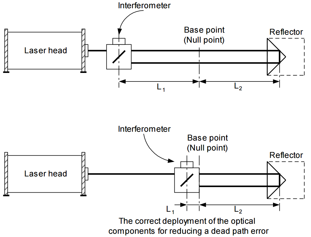
A dead path error is an error associated with the change in environmental parameters during a measurement. This error occurs when some part of the light path (a dead path) is not included in the temperature (both air and base), pressure and humidity compensation. The dead path of the light path is a distance between the optical interferometer and the base (or the null point) of the measuring position (L1 on figure below). Let the position of the interferometer and the retro-reflector does not change. When there is a change in the air temperature, pressure or humidity, then the wavelength changes on the whole path length (L1 + L2). The path length changes also when the temperature of the base changes. But the correction system will use the correct wavelength only on the length L2 and will correct only this length. The correction will not be made on a dead path L1. In this way, the laser system will “move” the base point. A dead path error is the more severe the greater is the distance between the interferometer and the base point. This error is especially important in laser interferometers where the interferometer is build-up in a common casing with a laser head, because it is then very difficult to reduce a dead path.
AN ILLUSTRATION OF A DEAD PATH ERROR
3. Cosine error
If the laser beam is not parallel to a measured axis of a machine (i.e. the optical path is not properly adjusted) then a difference between the real distance and the measured distance occurs. This error of misalignment is known as a cosine error, because its magnitude depends on the angle between the laser beam and the axis of the machine (figure below).
THE BEAM UNALIGNMENT AS A CAUSE OF A COSINE ERROR
If, as a reflector a flat mirror is used, than the beam must be perpendicular to it. If the machine changes its position form point A to point B, then the beam stays perpendicular to the mirror, but moves on its surface. The distance measured by the laser interferometer , will be smaller, than the real distance , according to
The above equation is valid also when as a reflector a corn cube is used. The only method of eliminating the cosine error is a proper laser beam alignment done before a measurement.
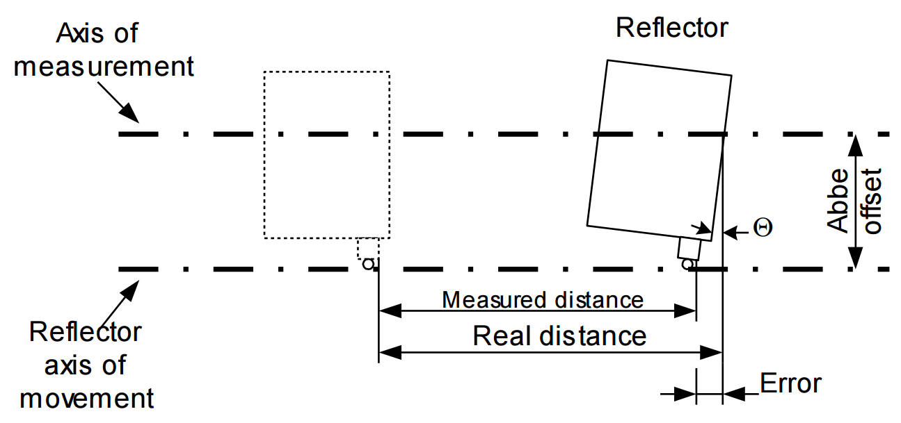
4. Abbe error
An Abbe error occurs when, during measurements, the measured part does not move perfectly straight and there appear angular movements, which cause sloping of the retro-reflector. The sloping of the reflector is the greater the longer is the distance between the axis of the measurement and the axis of movement. This distance is called An Abbe offset. Only the movements in the axis of the measurement are important (see fig. 17.6). An Abbe error may be avoided only when there are no angular movements of the retroreflector in the axis of the measurements.
AN ILLUSTRATION OF AN ABBE ERROR
5. Laser stability error
As was already mentioned, in laser measurements the laser wavelength instability changes directly the readout from the interferometer, e.g. a relative instability of the laser in the range of 1ppm, causes an error of 1um on every 1m of a measured distance. Therefore the laser instability error is important mainly in measurements in vacuum (where a refraction coefficient is constant) and when a low stability laser is used (e.g. a semiconductor laser). The stability of usually used in laser measurement systems, HeNe gas lasers is 0.02 ppm, so the stability error may be neglected.
6. Other errors
In some conditions, a noticeable error may be caused by the electronic part of the interferometer. As the electronics is used mainly for counting, the errors may be associated either with miscounting (some pulses are not counted) or with miscalculating (the calculations are made with finite precision).
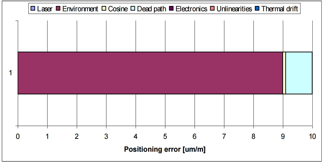
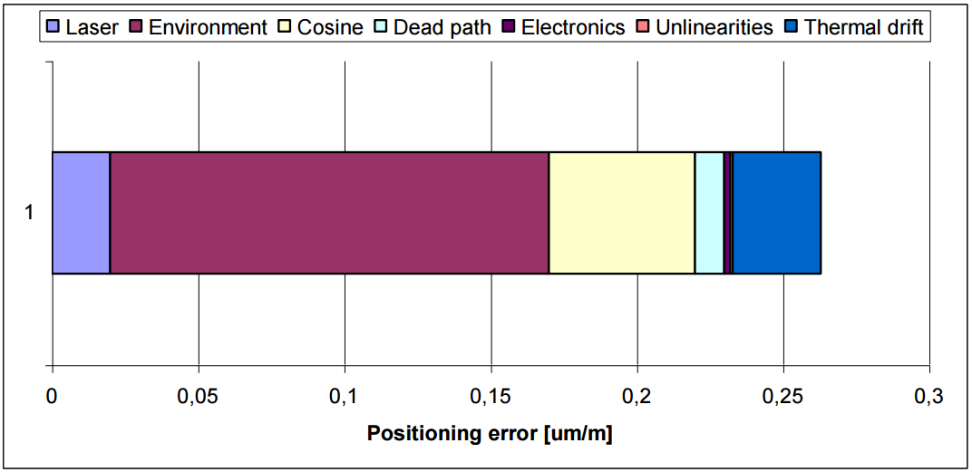
7. Summary
In order to show which of the errors influence the accuracy of a laser measurement system the most, an exemplary calculation of errors on a 1m long steel machine is shown below. Different scales of the charts should be taken into account.
A CALCULATION OF ERRORS FOR A LASER MEASUREMENT SYSTEM WITHOUT THE COMPENSATION OF THE ENVIRONMENT
A CALCULATION OF ERRORS FOR A LASER MEASUREMENT SYSTEM WITH THE COMPENSATION OF THE ENVIRONMENT
Positioning
Basis
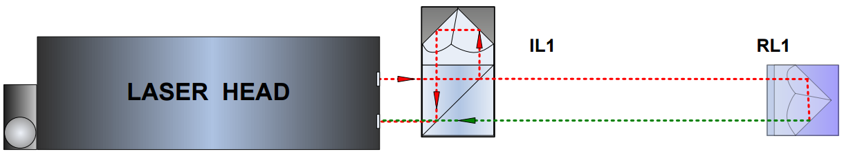
The Positioning measurement is the very basic measurement performed with the linear optical components: linear retroreflector RL1 and the linear interferometer IL1. Any change in the distance between IL1 and RL1 is detected by the laser head and shown in the HPI Software.
As it is illustrated in the Figure 5.2 both elements are normally aligned along the laser beam. Although IL1 is usually treated as a reference element with the movement of the RL1 measured but the configuration can also be reverse, i.e. RL1 can be stationary with IL1 being translated.
The distance L measured in the linear configuration depends significantly on the actual wavelength lair of the laser beam with the formula
,where N denotes the number of interference fringes, is the laser wavelength measured in vacuum and n(T,P,H) is the refraction coefficient of the air. The wavelength changes with the fluctuations of the parameters of the air: humidity, pressure and humidity. From the experimental formulas it may be obtained the refraction coefficient dependences on T, P and H in usual conditions (T=293K, P=1000hPa, H=50%):
The changes of the wavelength are compensated automatically by the HPI-3D laser head only if the TH sensor is used properly, i.e. placed near the laser beam path. The air pressure is measured inside the laser head.
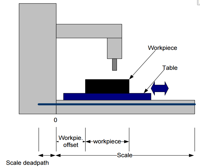
Temperature compensation
One of the important factors limiting the precision of every machine is the temperature. In the figure below there is schematically shown a milling machine. On the machine there is a work table with a workpiece. There is also schematically shown the measurement subsystem of the machine, i.e. the Scale. The position encoder (marked as Scale) is the part that is connected to the CNC control. It can be of different construction – magnetic, glass, laser, etc. Its expansion is corrected with positive sign in order to force the CNC control to leave the table in the same position despite the thermal expansion of the scale.
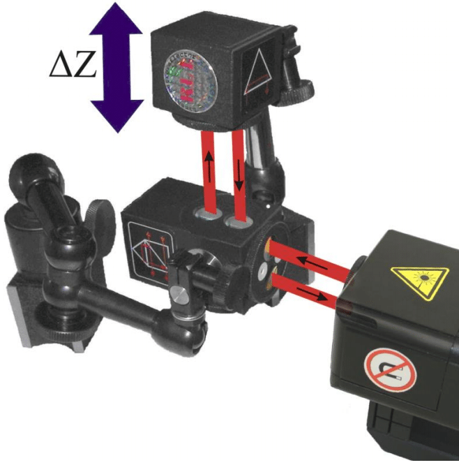
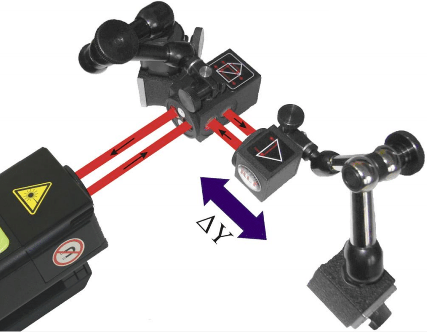
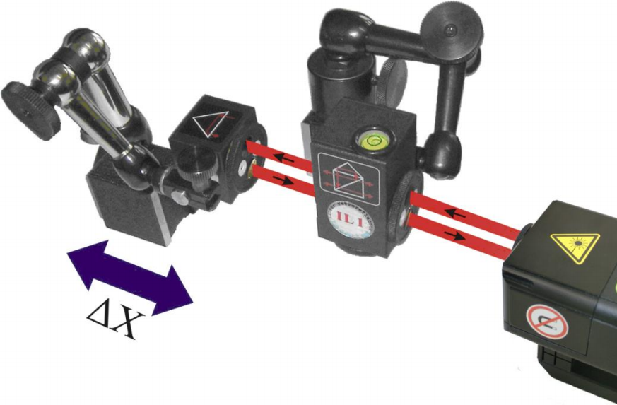
Setup Preparations
Positioning measurements require optical elements IL1 and RL1 to be aligned along laser beam. Each of the elements can be moved. During positioning measurements the Abbe, Dead Path and Cosine errors (for details – click here) have to be taken into consideration. The usage of the air temperature sensor and at least one base temperature sensor (T1 or T2 or T3) is absolutely necessary! More than one base temperature sensor should be used on long measurement axes, especially where a temperature gradient is possible.
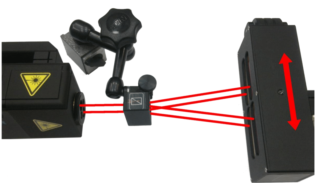
OPTICAL PATH SET UP FOR POSITIONING MEASUREMENTS IN Y AXIS (left),
OPTICAL PATH SET UP FOR POSITIONING MEASUREMENTS IN X AXIS (center),
OPTICAL PATH SET UP FOR POSITIONING MEASUREMENTS IN Z AXIS (right)
Velocity
For velocity measurements linear optics should be used. Necessary components are:
Laser Head
Power Supply
Linear interferometer IL1
Linear retro-reflector RL1
Optional elements are:
USB cable
Manual Strobe
Magnetic holder UM2
Tripod stand
Base temperature sensor
Air temperature sensor
Velocity measurements require optical elements IL1 and RL1 to be aligned along laser beam. Each of the elements can be moved. During velocity measurements the usage of the air temperature sensor is recommended. Base temperature sensors do not have to be used.
Velocity measurements can be performed not only along the laser beam (as shown in the figures above) but also in directions perpendicular to the laser beam. In those two configurations only the retro-reflector RL1 can be moved.
OPTICAL PATH SET UP FOR POSITIONING MEASUREMENTS IN Y AXIS (right),
OPTICAL PATH SET UP FOR POSITIONING MEASUREMENTS IN X AXIS (center),
OPTICAL PATH SET UP FOR POSITIONING MEASUREMENTS IN Z AXIS (left)
Straightness
Basis
In the HPI-3D device the straightness measurements can be performed with three different methods: Angular, Wollaston and 3D.
Angular method is designed to be used in base straightness measurements (like optical autocollimator);
Wollaston method is designed for “movement in space” measurements – e.g. the movement of a machine table or working tool can be characterized;
3D method is used for rapid estimation of “movement in space” – like Wollaston method but the measurement is performed in the three axes at once.
The main parameters of those methods are described in the Lasertex Technical Data below.
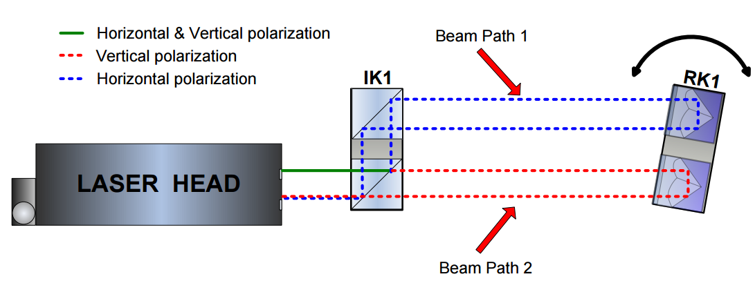
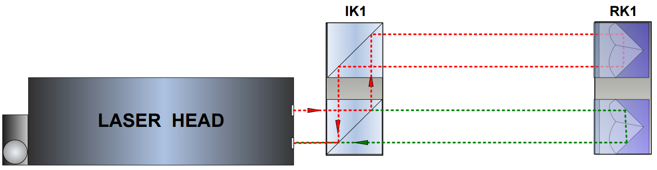
The operation of the HPI-3D with the angular optics used is shown in the figure below. The laser outputs the laser beam consisting of two polarizations: Horizontal (H) and Vertical (V). It is possible because beam spliter inside IK1 is set at the Brewster angle. Both beams are directed into the measurement path but are parallel shifted by 1’’ or 2’’ distance (depending on the version).
When the distance between optical elements altered then the frequency of both beams is changed according to the Doppler Effect. The laser head does notice a movement only if there is a rotation of IK1 versus RK1, i.e. when there is difference in lengths of beam paths. The measured distance can then be used to obtain either the rotation angle (pitch or yaw of the machine) or the vertical movement of the optical component (IK1 or RK1).
The laser head with angular optics is insensitive to linear movements.
In the figure on the right is showning schematically an RK1 on a carriage with all parameters important for calculation. For the clarity the position of IK1 is treated as a reference. The meaning of the parameters is:
L – base length;
s – distance between beams on IK1 and RK1 elements;
x – distance measured by the Laser Head
α– angular rotation of RK1 element
h – difference in height between two measurement points
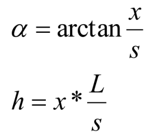
The Laser Head measures the parameter x while the distance between beams s and the base length L must be set in the parameters of the HPI Software. Then the rotation angle α and the movement in the vertical direction h can be calculated from:
Application notes
The angular optics can be used for:
Measurement of pitch or yaw of a machine
Measurement of straightness of a machine bed
Measurement of small angles
Measurement of pitch or yaw of a machine and straightness of a machine bed
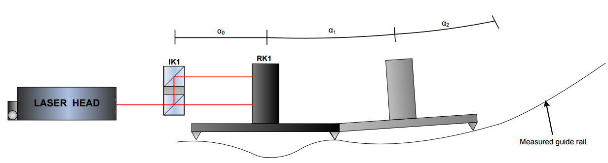
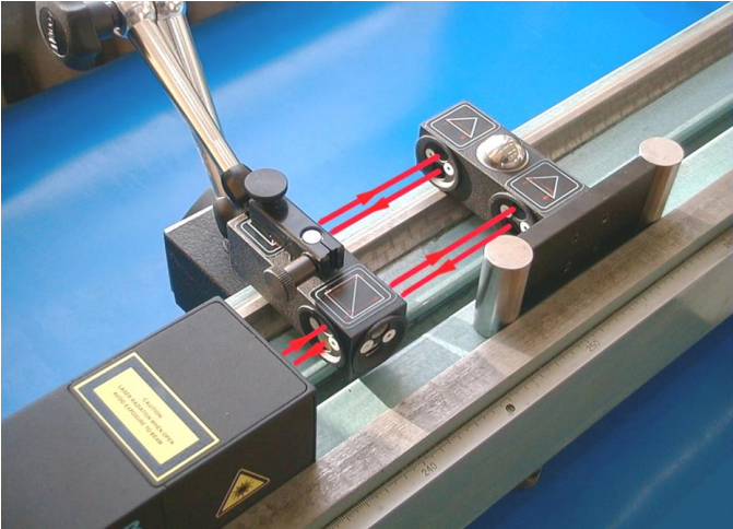
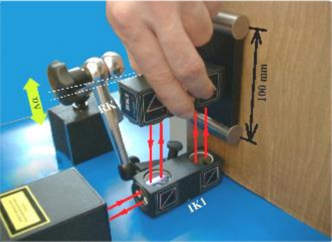
The explanation of the first two applications is shown in the figure below. The RK1 mounted on a carriage is translated over the measured guide rail. Every length of the carriage (usually 100mm) a measurement is performed. Formulas from previous chapterare then used for calculation of the angles (for pitch/yaw measurements) or the vertical translations (for straightness measurements).
It is worth to notice that such straightness measurement method requires proper choice of measurement points. Choosing points denser than the carriage size results in excessive values of the straightness errors (the shape of the error is proper).
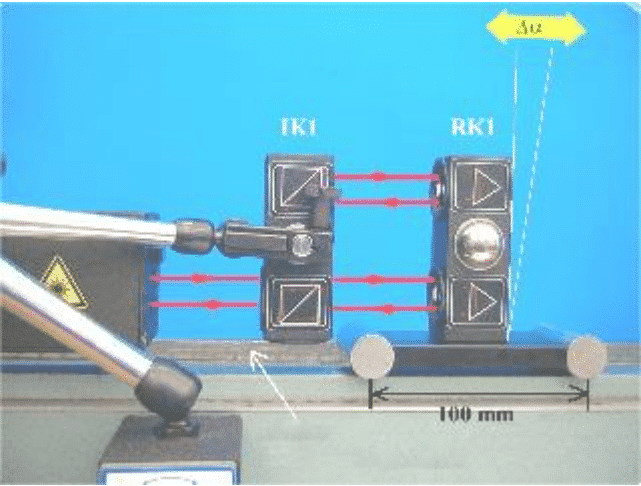
Choosing points too sparse may effect both the shape and the value of the error as shown in the figure below. In this special case because of too sparse measurement points the laser will not notice the change in the shape of the guide rail – the measured distance between beams will not change!
Measurement of small angles
The measurement of small angles allows very accurate measurements of small rotations if two conditions are met:
1. measured angle is within ±5 degrees
2. distance between RK1 and the laser head does not change more than a few centimeters.
The second limitation comes from the heterodyne effect present in the HPI-3D laser. This effect influences the angle according to (Δl is the change of distance between the laser and RK1 during measurements) :
Flatness
Basis
For flatness measurements the angular optics plus additional mirrors should be used. Necessary components are:
Laser Head
Power Supply
Angular Interferometer IK1
Angular Retro-reflector RK1
Two Beam Benders ZK1
Optional elements are:
USB cable
Manual Strobe
Magnetic holder UM2
Tripod stand
Air temperature sensor
Base temperature sensor
THE ELEMENT SET FOR THE FLATNESS MEASUREMENTS (IK1, RK1 AND ZK1)
Flatness measurements require that optical elements IK1 and RK1 are aligned along laser beam as shown in the figure below for the first axis. Element IK1 is stationary and element RK1 is moved. Other axes can be measured with the use of one or two beam benders with constant position of the laser head, or by moving the position of the laser head. In both cases realignment of the IK1 and RK1 components is required. It is recommended to use the option with constant position of the laser head because it simplifies the realignment process.
During flatness measurements the usage of the air temperature sensor is recommended. Base temperature sensors do not have to be used.
OPTICAL PATH SET UP FOR FLATNESS MEASUREMENTS IN ONE OF AXES.
Squareness
The choice of optical elements necessary for squareness measurements depends on the selected measurement method: i.e. 3D or Wollaston. If 3D method is used then the linear optics plus right angle etalon should be used. In this case the necessary components are:
Laser Head
Power Supply
Linear Interferometer IL1
Linear Retro-reflector RL1
Right angle etalon RE3D or REW
In the case of the Wollaston type measurement the necessary components are:
Laser Head
Power Supply
Wollaston prism WP2
Wollaston retro-reflector WRP2
Right angle etalon REW
For both methods the optional elements are similar:
USB cable
Manual Strobe
Magnetic holder UM2
Tripod stand
Air temperature sensor
Base temperature sensor
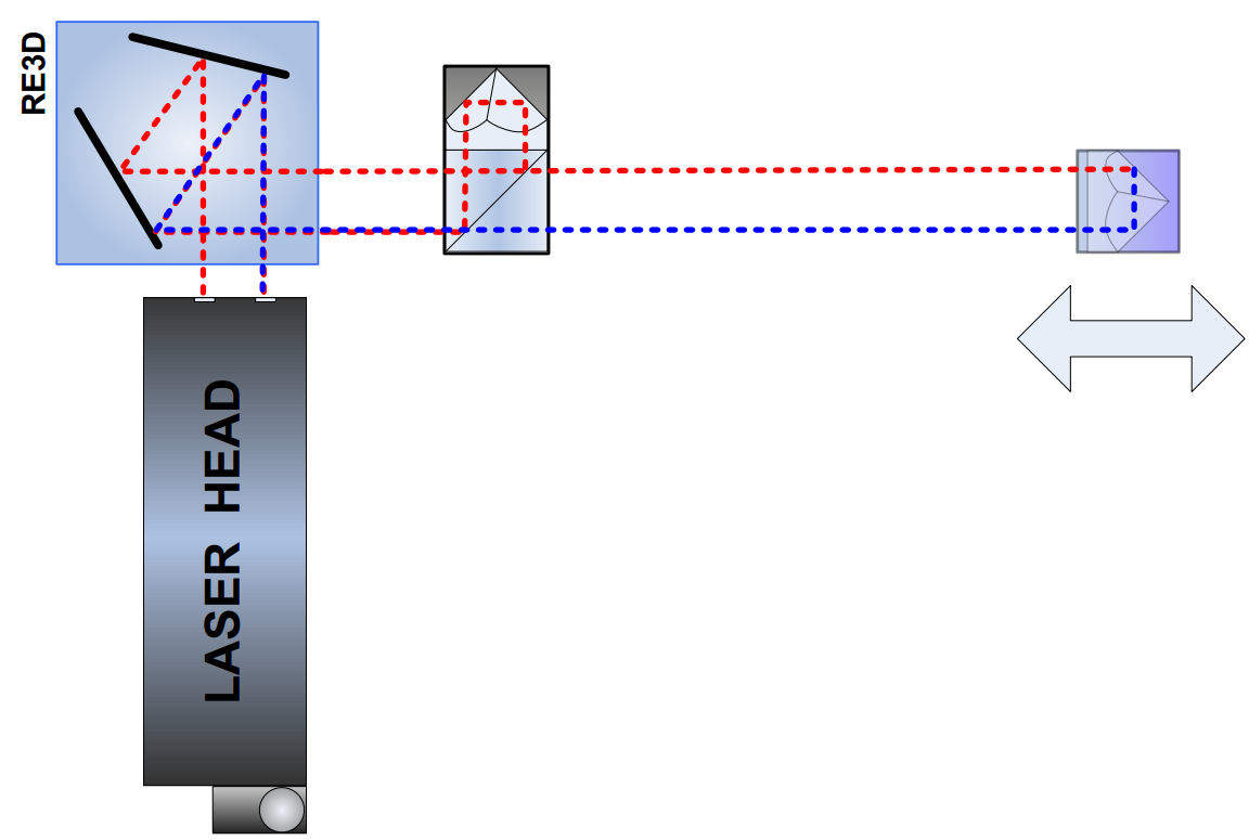
Squareness measurements based on the 3D method require optical elements IL1 and RL1 to be first aligned along the laser beam as shown in the figure below. The element RL1 should be moved. Obtained results of the axis straightness should be saved for further processing.
In the next phase of the measurements the beam should be directed to the perpendicular axis with the use of right angle etalon RE3D or REW.
OPTICAL PATH SET UP FOR 3D SQUARENESS MEASUREMENTSFIRST AXIS
Be careful not change the position of the laser head during alignment of the laser path – the beam path has tobe aligned only with the rotation of either the RE3D or the REW element!
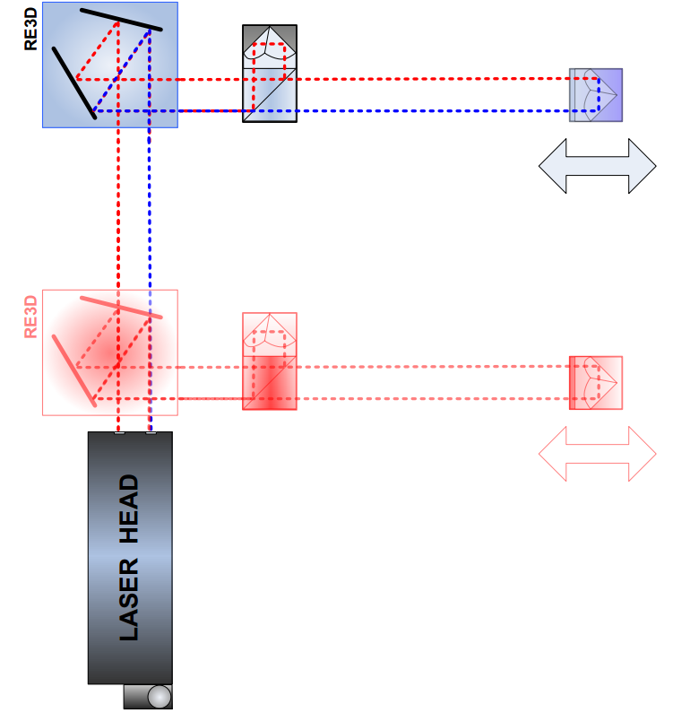
The optical configuration is shown in the figure below. The measurement of the axis straightness should be performed with the movement of the RL1 element.
OPTICAL PATH SET UP FOR 3D SQUARENESS MEASUREMENTS- SECOND AXIS
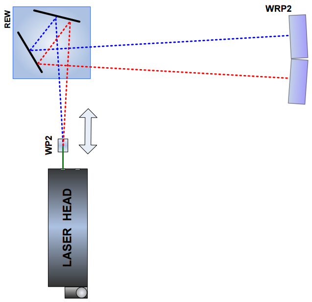
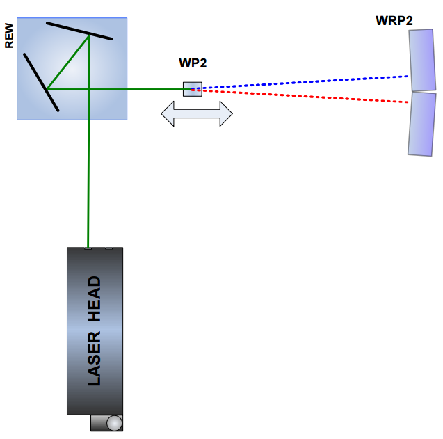
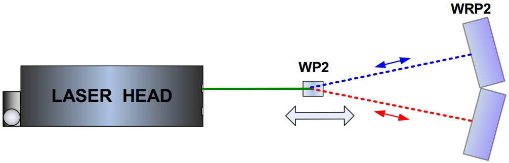
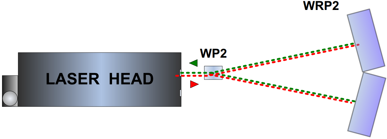
Wollaston squareness measurements require optical elements WP2 and WRP2 to be aligned along laser beam as shown in the figures 10.3A and 10.3B. The beam should be directed to the perpendicular axis with the use of right angle etalon REW. The measurements consist of two parts. In the first part the WP2 is moved between the laser head and the REW prism (Fig. 10.3A). During the second part the WP2 should be placed between REW and WRP2
OPTICAL PATH SET UP FOR WOLLASTONE SQUARENESS MEASUREMENTS – SCHEMATIC FOR FIRST AXIS. RETURN BEAMS NOT DRAWN FOR FIGURE CLARITY.
OPTICAL PATH SET UP FOR WOLLASTONE SQUARENESS MEASUREMENTS – SCHEMATIC FOR SECOND AXIS. RETURN BEAMS NOT DRAWN FOR FIGURE CLARITY
The element WRP2 MUST NOT be moved during measurements. The laser head and the REW should also be not touched during both parts of the measurement.
During squareness measurements the usage of the air temperature sensor is recommended. Base temperature sensors do not have to be used.
Parallelizm
The choice of optical elements necessary for parallelism measurements depends on the selected measurement method: i.e. 3D or Wollaston. If 3D method is used then the linear optics plus right angle etalon should be used.
3D method
In this case the necessary components are:
Laser Head
Power Supply
Linear Interferometer IL1
Linear Retro-reflector RL1
Right angle etalon RE3D
OPTICAL PATH SET UP FOR 3D PARALLELISM MEASUREMENTS-SCHEMATIC FOR AXIS 1.
OPTICAL PATH SET UP FOR 3D PARALLELISM MEASUREMENTS-SCHEMATIC FOR AXIS 2.
Parallelism measurements based on the 3D method require optical elements IL1 and RL1 to be aligned along laser beam as shown in the figures above. The element RL1 should be moved. The beam should be directed to the perpendicular axis with the use of the right angle etalon RE3D.
Wallastone method
Wollaston parallelism measurements require optical elements WP2 and WRP2 to be aligned along laser beam as shown in the figure 11.3. The element WP2 should be movedfirst along Axis 1 and then along Axis 2. No right angle prism is necessary for this measurement.
OPTICAL PATH SET UP FOR WOLLASTONE PARALLELISM MEASUREMENTS – SCHEMATICS
During parallelism measurements the usage of the air temperature sensor is recommended. Base temperature sensors do not have to be used.
Dynamic
Dynamic measurements of distance, velocity or acceleration
For dynamic measurements of distance, velocity and acceleration the linear optics should be used. Necessary components are:
Laser head
Power Supply
Linear interferometer IL1
Linear retro-reflector RL1
Dynamic measurements of distance, velocity and acceleration require optical elements IL1 and RL1 to be aligned along laser beam as shown in the figure below. The laser measures the difference of distance between optical elements (i.e. IL1 and RL1). During dynamic measurements the usage of the air temperature sensor is recommended. Base temperature sensors do not have to be used.
Dynamic measurements can be performed not only along the laser beam but also in directions perpendicular to the laser beam. These configurations are shown in the figures below. In those two configurations only the retro-reflector RL1 can be moved.
Dynamic measurements of angle
For dynamic measurements of angle the angular optics should be used. Necessary components are:
Laser Head
Power Supply
Angular Interferometer IK1
Angular Retro-reflector RK1
Dynamic measurements of angle require optical elements IK1 and RK1 to be aligned along laser beam as shown in the figure 13.5. Each of the elements can be moved. During Angular straightness measurements the usage of the air temperature sensor is recommended. Base temperature sensors do not have to be used.
Angular straightness measurements can be performed not only along the laser beam (as shown in the figures below) but also in directions perpendicular to the laser beam. These configurations are shown in the figures 13.7 and 13.8. In those two configurations only the retro-reflector RK1 can be moved.
OPTICAL PATH SET UP FOR ANGULAR DYNAMIC MEASUREMENTS IN Y AXIS (left) OPTICAL PATH SET UP FOR ANGULAR DYNAMIC MEASUREMENTS IN Z AXIS (center) OPTICAL PATH SET UP FOR ANGULAR DYNAMIC MEASUREMENTS IN X AXIS (right)
Dynamic measurements of straightness (Wollaston)
For dynamic measurements of straightness the Wollaston optics should be used. Necessary components are:
Laser Head
Power Supply
Wollaston prism WP2
Wollaston retro-reflector WRP2
Dynamic straightness measurements require optical elements WP2 and WRP2 to be aligned along laser beam as shown in the figure above. Each of the elements can be moved. During dynamic straightness measurements the usage of the air temperature sensor is recommended. Base temperature sensors do not have to be used. Dynamic straightness measurements can be performed in two configurations – horizontal X or vertical Z. In the configuration X only the straightness of path in the X axis is measured. The same situation is with the Z setup.
Lasertex HPI-3D laser interferometer. Range 0-30M ( 80M Available) Resolution 0.1 nm, Accuracy 0.4 ppm, With Tripod, Wireless connection to a PC, Native resolution of 100 pm, Measurements of vibration up to 100 kHz, Dynamic measurements up to 100 000 samples per second, measurable velocity up to +/- 7m/s, ntegrated environment compensation unit with wireless sensors.


 The operation of the HPI-3D with the angular optics used is shown in the figure below. The laser outputs the laser beam consisting of two polarizations: Horizontal (H) and Vertical (V). It is possible because beam spliter inside IK1 is set at the Brewster angle. Both beams are directed into the measurement path but are parallel shifted by 1’’ or 2’’ distance (depending on the version).
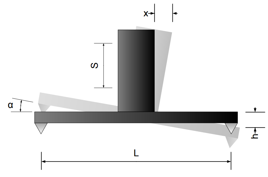
 The explanation of the first two applications is shown in the figure below. The RK1 mounted on a carriage is translated over the measured guide rail. Every length of the carriage (usually 100mm) a measurement is performed. Formulas from previous chapterare then used for calculation of the angles (for pitch/yaw measurements) or the vertical translations (for straightness measurements).
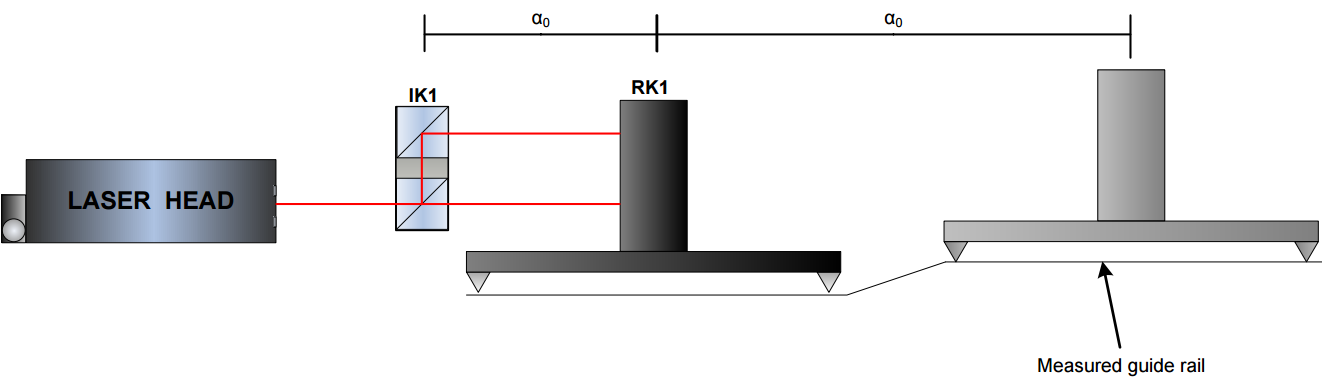 Choosing points too sparse may effect both the shape and the value of the error as shown in the figure below. In this special case because of too sparse measurement points the laser will not notice the change in the shape of the guide rail – the measured distance between beams will not change!
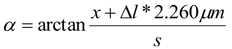 The second limitation comes from the heterodyne effect present in the HPI-3D laser. This effect influences the angle according to (Δl is the change of distance between the laser and RK1 during measurements) :

 OPTICAL PATH SET UP FOR 3D SQUARENESS MEASUREMENTSFIRST AXIS
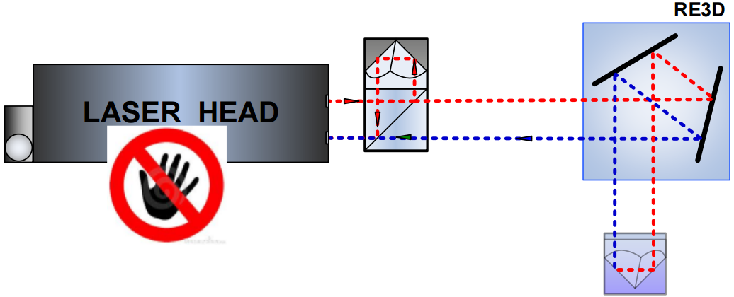


