
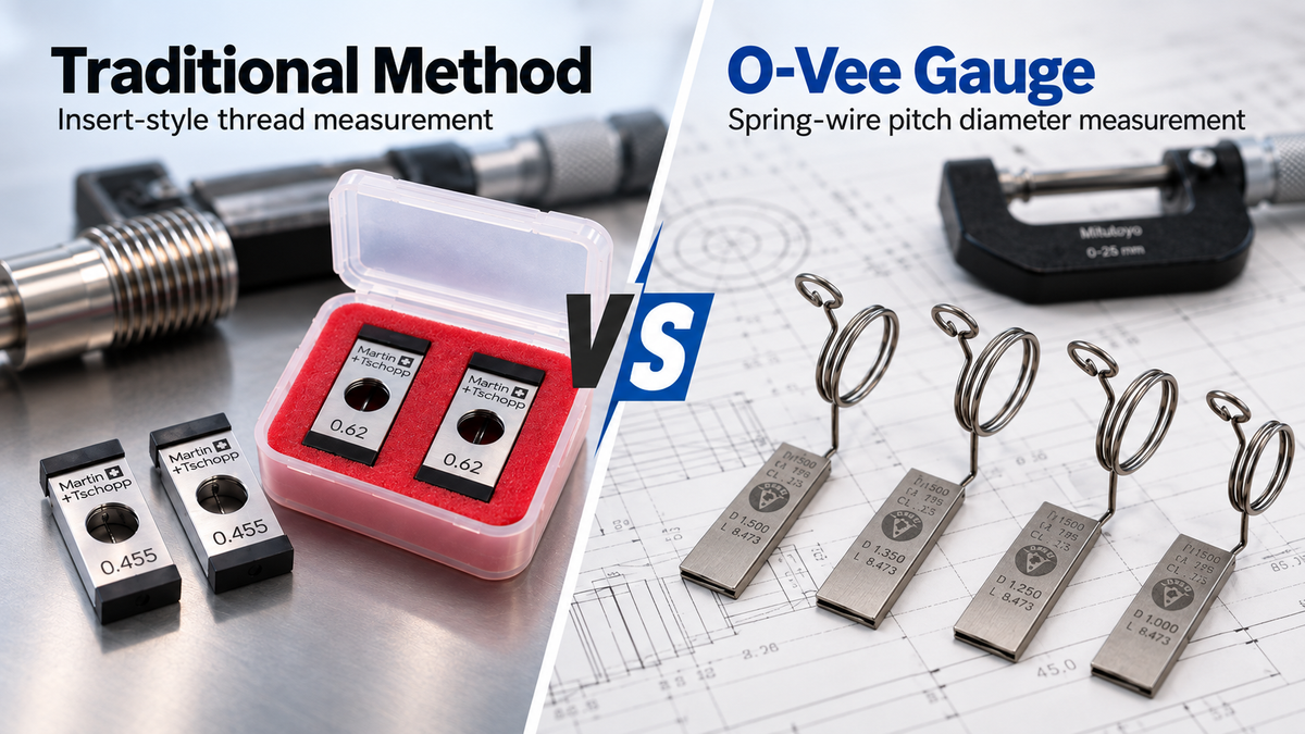
Beyond GO/NO-GO: O-Vee Gauges and the Measurement of Thread Pitch Diameter
Abstract
Thread inspection is a fundamental component of dimensional quality control in precision manufacturing. Conventional inspection methods, including thread pitch gauges, GO/NO-GO ring and plug gauges, and the three-wire method, remain widely used because of their established reliability and suitability for different production environments. However, these techniques vary considerably in the type and depth of information they provide. While functional gauges generally produce qualitative pass/fail results, dimensional techniques are capable of providing quantitative information regarding thread geometry and pitch diameter.
O-Vee spring thread gauges represent an alternative approach for the numerical assessment of external thread pitch diameter. By integrating calibrated measuring elements within a flexible spring structure, the system is intended to reduce the handling complexity associated with conventional loose-wire methods while retaining the ability to derive numerical pitch diameter values. This article examines the operating principles, practical applications, advantages and limitations of O-Vee gauges in comparison with established thread inspection methods.
1. Introduction
Threaded components are widely employed in mechanical assemblies across precision engineering, automotive manufacturing, aerospace, tooling and general industrial production. The dimensional conformity of threaded interfaces has a direct influence on assembly compatibility, load distribution, mechanical stability and long-term functional performance.
Thread inspection can broadly be divided into two categories: functional verification and dimensional measurement. Functional verification is primarily concerned with determining whether a threaded component satisfies specified assembly limits, whereas dimensional measurement provides numerical information regarding individual characteristics of the thread geometry.
Among the most important dimensional parameters is pitch diameter, as this characteristic has a direct influence on the fit between mating threaded components. The selected inspection method therefore depends not only on the required level of accuracy, but also on whether the objective is rapid production screening, thread identification, process monitoring, calibration or detailed dimensional analysis.
Traditional inspection systems remain appropriate for many applications. Nevertheless, where quantitative measurement is required, manufacturers may benefit from methods that provide numerical data without introducing excessive complexity into the inspection process.
2. Traditional Thread Inspection Methods
2.1 Thread Pitch Gauges
Thread pitch gauges, also referred to as thread combs or leaf gauges, are primarily intended for the identification of thread pitch and general thread form.
Each leaf incorporates a defined tooth profile corresponding to a particular thread pitch. During inspection, the operator places the selected leaf against the thread and visually assesses whether the profile corresponds with the thread flanks.
The principal advantages of thread pitch gauges are simplicity, portability and rapid application. They are therefore particularly useful for identifying unknown threads or verifying nominal pitch during maintenance and workshop inspection.
However, thread pitch gauges do not provide quantitative information relating to pitch diameter, major diameter, minor diameter or actual tolerance deviation. Their function is therefore primarily classificatory rather than metrological.
2.2 GO/NO-GO Thread Gauges
GO/NO-GO gauges are widely used for functional verification in manufacturing environments.
For external threads, thread ring gauges are commonly employed, whereas internal threads are typically inspected using thread plug gauges. The GO element verifies compliance with one tolerance boundary, while the NO-GO element is used to confirm that the component does not exceed the opposite functional limit.
The main advantage of this method is its speed. A trained operator can rapidly determine whether a threaded component falls within predefined acceptance limits.
The resulting output, however, is essentially binary. The component either satisfies the specified functional condition or it does not.
This approach is highly effective for production screening and final inspection, but it does not indicate the actual dimensional position of the component within the tolerance band. As a result, two components may both satisfy the same GO/NO-GO requirement while possessing different actual pitch diameters.
This limits the usefulness of functional gauges for detailed process monitoring, tool wear analysis and statistical evaluation.
3. The Three-Wire Method
The three-wire method is an established technique for the precise measurement of external thread pitch diameter.
Three calibrated wires of appropriate diameter are positioned within the thread grooves, after which a micrometer is used to measure over the wires. The resulting measurement is then converted into pitch diameter using the appropriate geometrical relationship.
When correctly applied, the three-wire method can provide highly accurate dimensional results and is widely recognised within precision metrology.
However, the technique introduces several practical considerations. These include the selection of appropriate wire diameter, correct positioning of the wires, prevention of movement during measurement, maintenance of consistent measuring force and accurate calculation of the resulting pitch diameter.
The handling of three separate wires may also increase setup time and contribute to operator-dependent variability, particularly in routine production environments.
For these reasons, the three-wire method is highly suitable for controlled metrology applications, but may be less convenient whe![]() re repeated measurements are required directly within manufacturing operations.
re repeated measurements are required directly within manufacturing operations.

4. O-Vee Spring Thread Gauge Measurement Principle
O-Vee spring thread gauges are designed to provide a more convenient method of obtaining numerical pitch diameter measurements for external threads.
Rather than requiring the operator to position three independent measuring wires manually, calibrated measuring elements are incorporated into a flexible spring-type structure. The gauge is positioned around the external thread, allowing the measuring elements to contact the thread flanks in a controlled configuration.
Once the gauge is correctly seated, a conventional external micrometer is used to measure across the external measuring surfaces.
The resulting micrometer measurement can then be converted into pitch diameter by applying the calibration constant associated with the individual O-Vee gauge.
The basic relationship may be expressed as:
Dp = Mm − C
where:
Dp = pitch diameter
Mm = measured value obtained using the micrometer
C = calibrated gauge constant
Mm = measured value obtained using the micrometer
C = calibrated gauge constant
This method therefore provides a numerical result while reducing the need to manipulate individual loose wires.
The ability to obtain quantitative pitch diameter values can be particularly useful where the objective extends beyond simple conformance verification.
5. Importance of Numerical Pitch Diameter Measurement
Functional gauging establishes whether a thread satisfies specified tolerance conditions. Numerical dimensional measurement, by contrast, provides information regarding the actual position of the measured component within those tolerance limits.
For example, where a permitted pitch diameter range extends from 19.920 mm to 19.950 mm, a functional gauge may confirm that a component is acceptable. A quantitative measuring system could additionally indicate that the actual measured pitch diameter is 19.947 mm.
Although the component remains within tolerance, the numerical result indicates that the manufacturing process is approaching one boundary of the permissible range.
Such information may support:
- tool wear monitoring;
- machining offset adjustment;
- identification of dimensional drift;
- first-off inspection;
- process optimisation;
- statistical process control;
- reduction of scrap;
- batch-to-batch comparison; and
- documented dimensional traceability.
Quantitative thread measurement may therefore contribute to preventive process control rather than relying solely on final pass/fail screening.
6. Comparison of O-Vee Gauges and Traditional Thread Gauging
The principal distinction between O-Vee gauges and conventional functional thread gauges lies in the type of information generated.
| Characteristic | O-Vee Spring Thread Gauge | Traditional GO/NO-GO Gauge |
| Measurement output | Numerical pitch diameter | Pass/fail result |
| Measurement principle | Micrometer measurement over calibrated contact elements | Functional engagement with threaded component |
| Process monitoring capability | Suitable for numerical trend analysis | Limited |
| Tool wear monitoring | Possible through repeated dimensional measurement | Indirect only |
| Inspection speed | Relatively rapid | Very rapid |
| Operator training | Moderate | Low |
| Additional equipment | External micrometer required | Generally self-contained |
| Statistical data collection | Numerical values available | Primarily categorical data |
| Primary purpose | Dimensional measurement | Functional verification |
The two systems should not necessarily be regarded as direct substitutes.
Instead, each provides a different form of quality information and may therefore be appropriate at different stages of the manufacturing process.
7. Applications of GO/NO-GO Gauges
GO/NO-GO gauges remain highly appropriate where rapid and reliable functional verification is required.
Typical applications include:
- high-volume production inspection;
- final acceptance inspection;
- assembly verification;
- operator-level quality control;
- sorting of conforming and non-conforming components; and
- repetitive manufacturing environments.
Where the primary requirement is to determine whether a thread is functionally acceptable, numerical dimensional information may not be necessary.
In such circumstances, GO/NO-GO gauging provides an efficient and well-established inspection method.
8. Applications of O-Vee Spring Thread Gauges
O-Vee gauges may provide additional value where the dimensional condition of the thread must be quantified.
Potential applications include:
- CNC machining;
- thread grinding;
- precision engineering;
- tool manufacture;
- automotive component production;
- aerospace component production;
- first-off inspection;
- process development;
- tool wear monitoring;
- quality laboratories; and
- dimensional process control.
For example, during CNC production of an external thread, repeated pitch diameter measurements may reveal gradual dimensional movement caused by tool wear.
Where a numerical trend is available, corrective action may be taken before components begin to exceed tolerance limits.
This represents a different quality-control function from that provided by final pass/fail inspection alone.
9. O-Vee Gauges and the Three-Wire Method
A more direct comparison can be made between O-Vee spring gauges and the traditional three-wire method, as both approaches are intended to support numerical determination of pitch diameter.
The principal difference concerns handling and measurement setup.
The three-wire method requires individual measuring wires to be positioned correctly within the thread during measurement. This can require considerable operator skill, particularly when working with small components or fine thread pitches.
By contrast, the O-Vee system retains its measuring elements within a single spring structure.
This integrated arrangement can simplify positioning and may improve measurement consistency during repeated inspection.
Nevertheless, both approaches require appropriate measuring technique, a suitable micrometer and correct interpretation of the resulting measurement.
The O-Vee method should therefore be regarded as a means of simplifying the practical implementation of pitch diameter measurement rather than eliminating the need for sound metrological practice.
10. Choosing the Appropriate Thread Inspection Method
The specific metrological objective should determine the selection of an appropriate thread inspection method, as no single inspection technique suits all applications.
When the primary requirement is identifying thread pitch, a thread pitch gauge provides a rapid, practical solution. For functional verification, calibrated GO/NO-GO ring and plug gauges remain widely used because they enable efficient assessment of whether a threaded component conforms to predefined tolerance limits.
When quantitative pitch diameter determination is required, use more precise dimensional methods. These may include the traditional three-wire method or a dedicated pitch diameter measurement system such as an O-Vee spring gauge.
In industrial quality control environments, multiple inspection methods are frequently used in combination rather than as mutually exclusive alternatives.
GO/NO-GO gauges may be applied for routine production inspection, numerical pitch diameter measurement may be introduced during first-off or process verification, and more comprehensive dimensional assessment may be conducted within a quality or calibration laboratory.
Such an integrated inspection strategy enables manufacturers to maintain production efficiency while simultaneously obtaining the quantitative data required for process monitoring, dimensional control and quality assurance.
11. Conclusion
Thread inspection remains an essential component of dimensional quality assurance within precision manufacturing.
Traditional tools such as thread pitch gauges and GO/NO-GO ring and plug gauges continue to provide effective solutions for rapid thread identification and functional verification. Their principal strength lies in simplicity, speed and suitability for routine production environments.
However, these methods do not ordinarily provide numerical information regarding actual pitch diameter.
Where detailed dimensional data are required, techniques such as the three-wire method or alternative pitch diameter measurement systems become more appropriate.
O-Vee spring thread gauges provide a means of obtaining quantitative pitch diameter measurements while reducing some of the handling complexity associated with loose measuring wires.
The principal value of this approach lies not in replacing all existing thread inspection techniques, but in complementing them by providing additional dimensional information.
For manufacturers seeking improved process monitoring, tool wear analysis, dimensional trend assessment and statistical quality control, numerical pitch diameter measurement may provide significant practical advantages.
The most appropriate inspection strategy therefore depends on the required output of the measurement process.
Where rapid functional verification is sufficient, GO/NO-GO gauging remains highly effective. Where greater dimensional visibility is required, numerical measurement methods such as the O-Vee system may provide a more informative basis for process control and quality assurance.
For further information regarding thread measurement, thread gauges, pitch diameter inspection or precision metrology solutions, contact MQS Metrology & Quality Services.